If you’ve ever stared at a 4 wire ignition coil diagram and felt like you were reading ancient hieroglyphics, you’re not alone. I’ve been there myself — standing in my garage with a multimeter in one hand and a printout in the other, trying to figure out which wire does what.
The good news is that once someone walks you through it clearly, reading these diagrams becomes second nature. And understanding your ignition coil wiring can save you hundreds of dollars at the mechanic when diagnosing misfires, rough idling, or that dreaded check engine light.
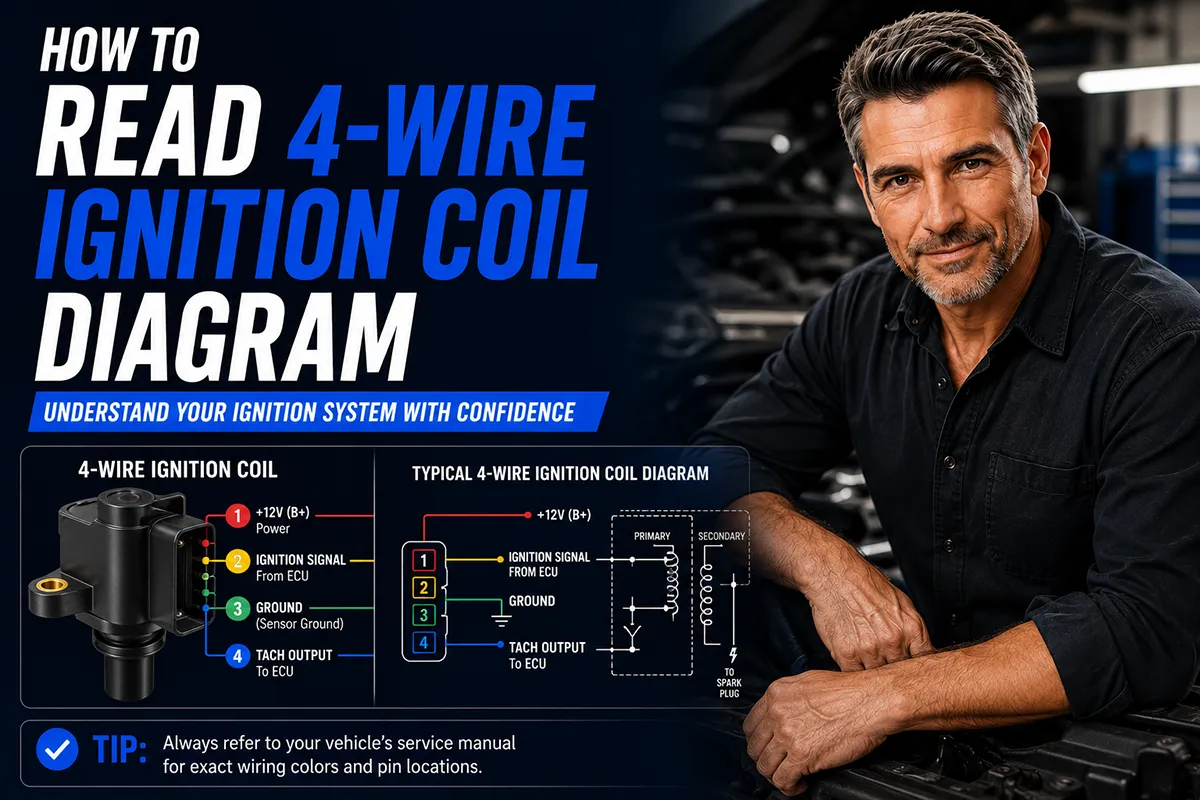
- A 4 wire ignition coil has two primary circuit wires (power and trigger/signal) and two secondary circuit wires (spark outputs to cylinders).
- The power wire (usually a thick red or white wire) supplies 12V from the ignition switch.
- The trigger wire (often from the ECU/PCM) tells the coil when to fire.
- The two secondary wires deliver high-voltage spark to paired cylinders in a “waste spark” system.
- You can test each wire with a basic multimeter to diagnose misfires and coil failures.
- Understanding this diagram helps you save money on diagnostics and avoid unnecessary part replacements.
Why Every Car Owner Should Understand Ignition Coil Wiring
I’ll be honest — I’m a tire guy at heart. I spend most of my days testing tread compounds and reviewing all-season radials. But over the years, I’ve learned that understanding the basics of your car’s electrical system is just as important as knowing when to replace your tires.
Here’s why: a misfiring ignition coil doesn’t just cause rough running. It sends unburned fuel into your exhaust, which can damage your catalytic converter — a repair that can easily cost $1,000 to $2,500. And misfires change how power is delivered to your wheels, which directly affects how your tires wear.
I’ve personally seen uneven tire wear patterns caused by persistent misfires that went undiagnosed for months. So when I started digging into ignition coil diagnostics, it was partly to protect the tire investments I recommend to readers every day.
What Is a 4 Wire Ignition Coil?
A 4 wire ignition coil is a type of ignition coil commonly found in modern vehicles that use a “waste spark” ignition system. Unlike older single-wire coils or newer coil-on-plug (COP) designs with different configurations, the 4 wire coil uses exactly four connections to do its job.
Two of these wires belong to the primary circuit (low voltage side), and two belong to the secondary circuit (high voltage side). The primary circuit is what you, the ECU, and the battery interact with. The secondary circuit is where the magic happens — stepping up that 12 volts to somewhere between 20,000 and 50,000 volts to create a spark.
In my experience working on vehicles from the late 1990s through the mid-2000s — particularly GM, Ford, and some Chrysler models — the 4 wire coil pack is extremely common. If your car uses a distributorless ignition system (DIS) with a coil pack rather than individual coil-on-plug units, there’s a good chance you’re dealing with a 4 wire setup.
Where You’ll Find 4 Wire Ignition Coils
These coils are most commonly found on:
- GM vehicles with 4-cylinder and 6-cylinder engines (Chevy Cavalier, Pontiac Grand Am, Buick Century)
- Ford vehicles with the Duratec and Zetec engines (Ford Focus, Ford Contour)
- Some Chrysler/Dodge vehicles with the 2.0L and 2.4L engines
- Various import vehicles from Toyota, Honda, and Hyundai from the late ’90s to mid-2000s
If you’re not sure whether your car uses a 4 wire coil, check your owner’s manual or simply trace the wires coming from your coil pack. Count four? You’re in the right place.
Breaking Down the 4 Wire Ignition Coil Diagram
Now let’s get into the meat of it. When you pull up a 4 wire ignition coil diagram — whether from a Haynes manual, AllData, Mitchell1, or a free resource online — you’ll see four labeled connections. Here’s what each one does.
Wire 1: The Power Supply Wire (B+ / 12V Ignition)
This is the wire that feeds your coil with battery voltage. It’s typically 12 volts when the ignition is in the “run” position. In most diagrams, this wire is colored red, pink, or white, though colors vary by manufacturer.
I always test this wire first when diagnosing coil issues. Grab your multimeter, set it to DC volts, connect the black lead to a good ground, and probe this wire with the key turned to “ON” (engine off). You should see roughly 11.5 to 14.5 volts. If you see zero or a very low voltage, you’ve likely got a wiring issue, a blown fuse, or a bad ignition relay — and the coil itself might be perfectly fine.
In the diagram, this wire usually comes from the ignition switch or a relay in the fuse box, passing through a fuse before reaching the coil. Follow the line backward from the coil to see the power source path.
Wire 2: The Trigger / Signal Wire (ECU/PCM Control)
This is where things get interesting. The trigger wire is the communication line between your car’s Engine Control Module (ECM) or Powertrain Control Module (PCM) and the coil. It’s the wire that tells the coil exactly when to fire.
In most 4 wire ignition coil diagrams, this wire runs directly from a specific pin on the ECM/PCM connector to the coil. It’s often colored green, blue, or dark green, but again, consult your vehicle-specific wiring diagram for accuracy.
The ECM sends a ground signal (or removes it) to trigger the coil. When the ECM grounds this wire, current flows through the primary coil winding, building up a magnetic field. When the ECM releases the ground, the magnetic field collapses, and the secondary coil generates the high-voltage spark.
I’ve found that when this wire has a poor connection or corrosion at the ECM connector, you’ll get intermittent misfires that can be incredibly frustrating to diagnose. During one of my own diagnostic sessions on a friend’s 2003 Chevy Cavalier, I spent hours chasing a random misfire that turned out to be a corroded pin on the ECM connector for this exact wire.
Wire 3: Secondary Output to Cylinder A
Now we move to the secondary (high voltage) side of the coil. Wire 3 carries the high-voltage spark from the coil to one of the paired spark plugs. In a waste spark system, each coil fires two spark plugs simultaneously.
On the diagram, this wire typically runs to a specific cylinder’s spark plug via a spark plug wire (also called an HT lead). For example, on a 4-cylinder engine with two coil packs, one coil might fire cylinders 1 and 4, while the other fires cylinders 2 and 3.
This pairing isn’t random. The cylinders are paired based on which pistons are at opposite points in the 4-stroke cycle. When one cylinder is on its compression stroke (where the spark is actually needed), the paired cylinder is on its exhaust stroke (where the spark is “wasted” — hence the name “waste spark”).
Wire 4: Secondary Output to Cylinder B
This is the mirror image of Wire 3. It carries the high-voltage spark to the paired cylinder. If Wire 3 goes to Cylinder 1, Wire 4 goes to Cylinder 4 (in our example above).
On the diagram, both secondary output wires will be shown connecting to spark plug symbols. They’ll usually be drawn as thicker lines than the primary wires to indicate they carry high voltage. Some diagrams use a different color or a dashed/bold line style to differentiate primary and secondary circuits.
I want to emphasize something important here: you should never probe or handle the secondary wires while the engine is running. We’re talking about 20,000 to 50,000 volts. While the amperage is low, the shock is extremely unpleasant and can be dangerous, especially if you have a heart condition. I learned this lesson the hard way during my early DIY days, and I don’t recommend repeating my mistake.
How the 4 Wire Ignition Coil Diagram Looks in Practice
Let me walk you through what a typical diagram looks like when you open it up, because the schematic symbols can be confusing if you’re not used to reading electrical diagrams.
Common Symbols You’ll See
- Coil symbol: Looks like a series of loops or a zigzag line (representing the wound wire inside the coil). You’ll usually see two sets — one for the primary winding (fewer loops) and one for the secondary winding (more loops).
- Ground symbol: Three horizontal lines stacked in decreasing width, like a small triangle. This shows where the circuit connects to the vehicle chassis.
- Connector/plug symbol: A small rectangle or circle where the wiring harness plugs into the coil.
- ECM/PCM box: A large rectangle labeled with pin numbers. The trigger wire will trace back to a specific pin here.
- Fuse symbol: A small rectangle with a number inside (like “15A”) showing the fuse rating.
- Spark plug symbol: Looks like a small gap between two lines — representing the spark plug gap where the spark jumps.
Reading the Diagram Step by Step
Here’s my personal method for reading any 4 wire ignition coil diagram. I’ve refined this over years of DIY diagnostics:
- Identify the coil. Find the coil symbol on the diagram. It’s usually centrally located.
- Trace the primary power wire. Follow the B+ or 12V line backward from the coil to the fuse box and ignition switch. Note the fuse number and rating.
- Trace the trigger wire. Follow this wire from the coil back to the ECM/PCM. Note the pin number — you’ll need this if you ever test the ECM connector.
- Identify the secondary outputs. Follow the two high-voltage wires from the coil to the spark plugs. Note which cylinders are paired.
- Check for ground paths. Some 4 wire coils ground through the trigger wire via the ECM. Others have a separate ground path. Make sure you understand which configuration your vehicle uses.
Comparison: 4 Wire Coil vs. Other Ignition Coil Types
To put the 4 wire coil in context, here’s how it compares to other common ignition coil configurations you might encounter:
| Feature | 4 Wire Coil (Waste Spark) | 2 Wire Coil-on-Plug (COP) | 3 Wire Coil-on-Plug (COP) |
|---|---|---|---|
| Number of Wires | 4 (2 primary + 2 secondary) | 2 (power + trigger) | 3 (power + trigger + ground) |
| Spark Plug Wires Needed | Yes (2 per coil) | No (sits directly on plug) | No (sits directly on plug) |
| Common Vehicles | Late ’90s to mid-2000s GM, Ford, Chrysler | Most modern vehicles (2005+) | Many Ford, Toyota, Honda models |
| Cylinders Per Coil | 2 (paired) | 1 (individual) | 1 (individual) |
| Avg. Replacement Cost (US) | $25–$80 per coil pack | $20–$60 per coil | $25–$70 per coil |
| Diagnostic Complexity | Moderate (4 wires to test) | Simple (2 wires to test) | Simple (3 wires to test) |
As you can see, the 4 wire coil is a bit more involved than modern COP designs, but it’s far from complicated once you understand the basics. And the parts are generally affordable — I’ve picked up quality replacement coil packs from AutoZone and O’Reilly for around $40 to $60.
How to Test a 4 Wire Ignition Coil Using the Diagram
Now that you can read the diagram, let me show you how to use that knowledge for actual diagnostics. This is where the rubber meets the road (pun very much intended for a tire blog).
Tools You’ll Need
- A digital multimeter (I use a basic Klein Tools MM400 — about $35 at Home Depot)
- Your vehicle-specific wiring diagram (Haynes manual, AllData, or free resources like AutoZone’s repair guides)
- A set of back-probing pins or T-pins (to test wires without damaging connectors)
- Safety glasses
Test 1: Checking the Power Supply Wire
- Turn the ignition key to the “ON” position (don’t start the engine).
- Locate the coil connector and identify the power supply pin using your diagram.
- Set your multimeter to DC volts (20V range).
- Probe the power supply wire at the connector. You should read approximately 12V (11.5–14.5V is normal).
- If you get 0V, check the fuse indicated in your diagram. If the fuse is good, trace the wire back toward the ignition switch for breaks or corrosion.
Test 2: Checking the Trigger Wire
- This test requires the engine to be cranking. Have a helper crank the engine while you test, or use a remote starter switch.
- Set your multimeter to DC volts.
- Probe the trigger wire at the coil connector.
- You should see a pulsing voltage — the meter reading will fluctuate or, on some digital meters, show an average voltage between 1V and 5V during cranking.
- If you get a steady 0V or a steady 12V with no pulsing, the ECM may not be sending the trigger signal. This could indicate an ECM issue, a bad crankshaft position sensor (which the ECM uses to time the trigger signal), or a wiring problem between the ECM and the coil.
Test 3: Checking Primary Coil Resistance
- Disconnect the coil connector and remove the coil from the vehicle (or at least disconnect it).
- Set your multimeter to ohms (Ω).
- Measure resistance across the two primary circuit pins (power and trigger). You should typically read 0.5 to 2.0 ohms for the primary winding. Check your service manual for the exact spec.
- If you read OL (open line/infinite resistance), the primary winding is broken and the coil needs replacement.
Test 4: Checking Secondary Coil Resistance
- With the coil disconnected, set your multimeter to a higher ohms range (20kΩ).
- Measure resistance across the two secondary output terminals (where the spark plug wires connect). You should typically read 6,000 to 15,000 ohms (6kΩ to 15kΩ).
- Again, OL means the secondary winding is open and the coil is toast.
I’ve personally used this testing process dozens of times, and it’s helped me correctly identify failed coils, bad wiring, and even a faulty ECM on one occasion. The key is always starting with the diagram so you know exactly what you’re testing and where.
Common 4 Wire Ignition Coil Problems and What the Diagram Tells You
In my experience, there are a handful of common issues that send people searching for ignition coil diagrams. Here’s what I’ve seen most often and how the diagram helps you solve each one.
Problem 1: Single Cylinder Misfire (P0301, P0302, P0303, P0304)
If your OBD-II scanner shows a misfire code for a specific cylinder, look at the diagram to see which coil serves that cylinder. Remember, in a waste spark system, one coil fires two cylinders. If only one of the paired cylinders is misfiring, the coil is probably fine — the issue is more likely the spark plug, spark plug wire, or fuel injector for that specific cylinder.
If both paired cylinders are misfiring (for example, P0301 and P0304 together), that’s a strong indicator that the coil serving that pair has failed.
Problem 2: Random/Multiple Misfire (P0300)
A P0300 code indicates misfires occurring across multiple cylinders without a clear pattern. In my experience, this is often not a coil issue — it’s more likely a fuel delivery problem, vacuum leak, or sensor issue. But the diagram can still help you rule out the coil by verifying the power supply wire. If the shared power wire has an intermittent connection, all coils could misfire randomly.
Problem 3: No Spark at All
When no cylinders are getting spark, the diagram helps you systematically check: Is the power wire getting 12V? Is the ECM sending trigger signals? If there’s power but no trigger, you might have a bad crankshaft position sensor — the ECM can’t calculate when to fire the coils without crank position data.
Problem 4: Coil Connector Corrosion
This is more common than you might think, especially in states with harsh winters where road salt gets everywhere. I’ve seen coil connectors in the Midwest and Northeast that were green with corrosion. The diagram shows you exactly which pins handle which function, so you can clean or repair the specific connections that are causing problems.
How Ignition Coil Health Affects Your Tires
I know what you’re thinking — “This is a tire blog. Why are we talking about ignition coils?” Fair question. But here’s the connection I’ve observed firsthand as a tire reviewer.
Misfiring engines deliver uneven power. When a cylinder isn’t firing properly, the engine produces inconsistent torque. This inconsistency gets transmitted through the drivetrain to the wheels. Over time, this can cause subtle but real differences in how your tires wear.
I’ve inspected tires on vehicles with chronic misfire issues and noticed irregular wear patterns — particularly cupping or scalloping — that weren’t explained by alignment, suspension, or inflation problems. Once the ignition issue was fixed, the tire wear normalized.
Additionally, a misfiring engine can cause your vehicle to pull slightly during acceleration. If you’ve recently installed new tires and notice the car doesn’t track straight under power, don’t immediately blame the tires or alignment. Check for misfires first.
Taking care of your ignition system is part of taking care of your tires. It’s all connected — literally and figuratively.
Where to Find Your Vehicle-Specific 4 Wire Ignition Coil Diagram
Not all diagrams are created equal, and using the wrong one can lead you down a frustrating rabbit hole. Here are the resources I trust and use personally:
- Haynes or Chilton Repair Manuals: Available at most auto parts stores for $20–$30. These have vehicle-specific wiring diagrams that are generally accurate and well-illustrated.
- AutoZone Free Repair Guides: Available online at autozone.com. The quality varies, but many include basic wiring diagrams at no cost.
- AllData DIY: A subscription-based service ($26.99/year for a single vehicle) that provides OEM-level diagrams and repair information. This is what many professional shops use, and I consider it well worth the investment.
- Mitchell1 DIY: Similar to AllData, with subscription-based access to professional-grade diagrams.
- YouTube: While not a “diagram” source per se, many excellent mechanics on YouTube walk through 4 wire coil testing with diagrams on screen. I especially recommend channels like South Main Auto and Scanner Danner for electrical diagnostics.
I strongly recommend against relying on random forum posts or generic diagrams that don’t specify your exact make, model, and engine. Wire colors, pin positions, and cylinder pairing can vary significantly even between model years of the same vehicle.
Pro Tips from My Personal Experience
After years of working on my own vehicles and helping friends diagnose ignition issues, here are some tips I wish someone had told me from the start:
Tip 1: Always Photograph the Connector Before Disconnecting
Before you unplug the coil connector, take a photo with your phone. This gives you a quick reference for wire colors and pin positions. I can’t tell you how many times this simple step has saved me from confusion during reassembly.
Tip 2: Don’t Assume Wire Colors Match the Diagram Perfectly
Aftermarket repairs, previous owners’ modifications, and even factory variations can mean the wire colors on your car don’t exactly match the diagram. Use the diagram as a guide, but always verify with your multimeter before drawing conclusions.
Tip 3: Replace Spark Plugs and Wires When You Replace the Coil
If you’ve diagnosed a failed coil, I always recommend replacing the spark plugs and spark plug wires at the same time. Worn plugs and wires can cause a new coil to work harder and fail prematurely. For a 4-cylinder engine, you’re looking at maybe $30–$60 in plugs and $20–$40 in wires — cheap insurance for protecting a new coil.
Tip 4: Use Dielectric Grease on the New Connector
A small dab of dielectric grease on the coil connector pins helps prevent future corrosion. This is especially important if you live in a humid climate or in salt-belt states. A tube of dielectric grease costs about $5 and lasts forever.
Tip 5: Clear Codes and Drive After Repairs
After replacing a coil or fixing a wiring issue, clear your OBD-II codes and drive the car for several days. Monitor for any return of misfire codes. If the codes come back, re-read the diagram and retest — you may have a secondary issue that was masked by the original coil failure.
When to Call a Professional
I’m a big advocate for DIY car maintenance, but I also believe in knowing your limits. Here are situations where I recommend taking your car to a qualified mechanic instead of diagnosing the 4 wire ignition coil yourself:
- You suspect an ECM/PCM failure. Testing and replacing an engine computer requires specialized tools and programming that most DIYers don’t have.
- You’re dealing with intermittent issues that you can’t reproduce. Intermittent electrical faults can require oscilloscope testing that goes beyond basic multimeter diagnostics.
- You’re not comfortable working around high-voltage secondary circuits. There’s no shame in this — safety comes first, always.
- Your vehicle uses a complex multiplexed wiring system. Some newer vehicles route coil signals through communication networks (like CAN bus) that require dealer-level diagnostic tools.
A good independent mechanic should charge between $80 and $150 for an ignition system diagnostic in most US markets. That’s money well spent if it means getting the right diagnosis the first time.
Wrapping It Up: Knowledge Is Power (Literally)
Learning how to read a 4 wire ignition coil diagram isn’t just about fixing a current problem — it’s about building the knowledge base that makes you a more informed car owner. Every time I’ve taken the effort to understand a new system in my vehicle, it has paid dividends down the road.
Your ignition system and your tires might seem like they live in different worlds, but they’re intimately connected through your drivetrain. A healthy ignition system means smooth, consistent power delivery, which means even tire wear, better fuel economy, and a safer driving experience.
So next time you see that check engine light flash and your OBD-II scanner shows a misfire code, don’t panic. Pull up your 4 wire ignition coil diagram, grab your multimeter, and work through it systematically. You might just save yourself a trip to the shop — and protect those new tires you invested in.
I hope this guide has been helpful. If you have questions about how ignition issues might be affecting your tire wear, or if you need tire recommendations for your specific vehicle, drop a comment below. I’m always happy to help fellow DIYers keep their cars running right from the coils to the contact patches.
Frequently Asked Questions
What do the numbers and letters on a 4 wire ignition coil diagram mean?
On a typical 4 wire ignition coil diagram, you’ll see labels like B+ (battery positive), GND (ground), TACH (tachometer signal), and the trigger or control wire from the ECU. Each wire corresponds to a specific terminal on the coil, and understanding these labels helps you trace the correct connections during diagnosis. I always recommend cross-referencing the diagram with your vehicle’s specific service manual since wire colors and pin positions can vary between US-market brands like Ford, GM, and Chrysler.
How do I identify the positive and negative terminals on a 4 wire ignition coil?
The positive terminal (B+) receives constant 12-volt power from the ignition switch, while the negative or control terminal connects to the ECU or ignition module that triggers the coil. On most 4 wire coil diagrams, the remaining two wires handle ground and a signal output for the tachometer or diagnostic system. I use a multimeter set to DC voltage to confirm which terminal reads roughly 12 volts with the key in the ON position, which eliminates any guesswork.
Can a faulty ignition coil cause misfires that feel like a tire vibration while driving?
Yes, a misfiring ignition coil can cause engine shudder and vibrations that many US drivers initially mistake for a tire balance issue or worn tires. If you feel a rhythmic vibration at highway speeds but your tires are properly balanced and inflated, it’s worth reading your 4 wire ignition coil diagram and testing each coil for proper resistance and signal output. I’ve seen this confusion firsthand, so I always recommend ruling out engine misfires with an OBD-II scanner before spending $80-$150 per tire on unnecessary replacements.
What tools do I need to test a 4 wire ignition coil using its wiring diagram?
You’ll need a digital multimeter, a test light, an OBD-II scanner, and your vehicle’s specific 4 wire ignition coil wiring diagram to properly diagnose coil issues. The multimeter lets you check primary resistance (typically 0.4–2 ohms) and secondary resistance (6,000–15,000 ohms) between the correct terminals shown on the diagram. These tools are affordable at US auto parts stores like AutoZone or O’Reilly, usually costing $20-$50 for a decent multimeter, and they’ll save you hundreds in unnecessary shop diagnostic fees.
What is the difference between a 2 wire and 4 wire ignition coil diagram?
A 2 wire ignition coil diagram only shows the primary power and trigger connections, which is common on older US vehicles with simple ignition systems. A 4 wire ignition coil diagram adds dedicated ground and signal output wires, which are standard on modern coil-on-plug and coil-near-plug setups found in vehicles like the Ford F-150 and Chevy Silverado. The extra wires give the ECU better control and diagnostic capability, so reading the 4 wire diagram correctly is essential for accurate troubleshooting on newer engines.
How does a bad ignition coil affect fuel economy and tire wear over time?
A failing ignition coil causes incomplete combustion that can reduce fuel economy by 10-20%, and the resulting engine misfires create uneven power delivery that puts inconsistent stress on your drivetrain and tires. Over time, persistent misfires on US highway drives can contribute to irregular tire wear patterns, especially on the drive wheels. I recommend addressing ignition coil issues promptly because a replacement coil typically costs $30-$80, which is far cheaper than premature tire replacement at $100-$200 per tire.
Where can I find the correct 4 wire ignition coil wiring diagram for my specific vehicle?
The best sources for an accurate 4 wire ignition coil diagram specific to your US-market vehicle are the factory service manual, AllData, Mitchell1, or free resources like AutoZone’s online repair guides. I always verify the diagram matches my exact year, make, model, and engine size because even slight trim-level differences can change the wiring configuration. Avoid relying solely on generic diagrams found in forums since incorrect wiring can damage your ECU, which is a repair that can cost $500-$1,500 at a US shop.

